Brand: Peerless Separation & Filtration

Desanding Hydrocyclones

Desanding Hydrocyclones

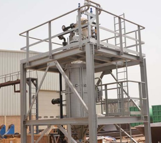
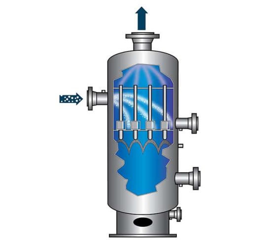
Desanding Hydrocyclones are pressure-driven cyclonic separators that utilize a certain pressure drop across the unit to force the separation of the solids from the bulk phase produced water or condensate. The feed stream, containing high amount of solids/ sand, enters the hydrocyclone through a tangential inlet under a pressurized condition. This is where it is forced into a spiral motion by the hydrocyclone’s internal profile. The internal conic shape of the liner causes the spinning/ swirling effect to accelerate (which effectively creates) high centrifugal forces, causing the denser solid particles to move to the outer wall of the hydrocyclone liner, while the lighter phase water or condensate is concentrated to the central core of the liner.

Solids continue to spiral down along the outer wall of the hydrocyclone to the bottom exit which is typically collected in an accumulator (could be integrated or a separate unit) for periodic disposal. The “desanded” water in the central core section reverses direction and is forced out through the central vortex towards the top of the Hydrocyclone.

Hydrocyclones are effectively centrifugal separators that rely on the differential density between the solids particle and the water to allow separation.

The efficiency of the separation is governed by four main factors:

  • Solid Particle Size
  • Differential Density
  • Viscosity of the Bulk Fluid
  • Gravity (or Centrifugal Force)

FEATURES u0026 BENEFITS

  • Compact design, replacing substantially larger equipment.
  • No moving parts and minimal maintenance
  • Ideal for use where space is minimal
  • Cyclonic liners are available in a range of alloys from Stainless steel, Alumina Ceramic, Polypropylene, Tungsten Carbide, Reaction Bonded Silicon Carbide
CECO Environmental

APPLICATIONS

  • Wellhead solids removal in multi-phase flow
  • Protection of equipment from blockage or erosion
  • Sand cleaning for overboard discharge
  • Polishing of water prior to re-injection

Deoiling Hydrocyclones

Deoiling Hydrocyclones

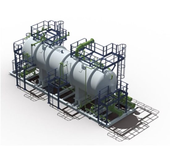
The horizontal deoiling hydrocyclone vessel with liners is designed to reduce the oil content of the incoming produced water prior to entering an optional degasser vessel. The horizontal arrangement allows easy access to the liners for inspection, installation, and replacement.

Liquid/liquid cyclones – On entering the cyclone tangentially, the fluid begins to spin. This creates a radial force that directs the heavier phase towards the edges of the cyclone and then out of the cyclone underflow owing to differential pressure. The less dense phase is concentrated in the centre of the cyclone before passing out of the cyclone overflow, again due to differential pressure.

Hydrocyclones are effectively centrifugal separators that rely on the differential density between the oil droplet and the water to allow separation. The efficiency of the separation is governed by five main factors:

  • Droplet/Particle Size
  • Differential Density
  • Viscosity of the Bulk Fluid
  • Gravity (or Centrifugal Force)
  • Distance

The reject from the hydrocyclone comes out in a counter current flow as a reverse spinning vortex. For an oil droplet to be removed it must make its way from the bulk fluid into the central core. The less distance the droplet must travel to get to this central core the higher the efficiency.

CECO Environmental

APPLICATIONS

Deoiler Hydrocyclones were developed for the offshore oil industry in the 1980s and rapidly became established as standard equipment used for recovery of oil from Produced Water streams in both onshore and offshore applications.

Walnut Shell Filters

Walnut Shell Filters

Nutshell filters are a type of tertiary treatment and are designed to provide an adsorption duty to low concentrations of free oil present as fine droplets.

They are therefore ideal for use as polishing units to be installed downstream of a hydrocyclone or flotation package prior to disposal or reinjection. Typically, they have a feed concentration limit of 50 mg/l for both oil and solids and a maximum solids mean size of 5 microns. Nutshell filters are most found in onshore installations due to their size and weight and the requirement for large ancillary items such as backwash storage tanks and recirculation pumps. They are however very simple systems with inexpensive media and their low requirement for operator intervention has made them ideal for use at onshore fields at remote locations.

Crushed nutshells constituting the packed bed within the vessels form an intricate network of tiny channels forcing the water to take an arduous flow path from the top to the bottom of the vessel. Multi-grade nutshell offers excellent oil coalescing and holding capacities and solids are removed by simply becoming trapped within the pore structure of the bed. As increasing quantities of oil are adsorbed by the nutshell surface capillaries, the fine solids removal capacity also increases. The filtered water is collected within the base of the vessel by a wedge-wire lateral system which routes the water out of the vessel. Nutshell filters provide a large adsorption area to allow easy adhesion of oil to the nutshell’s surface due to the presence of microscopic capillaries within the structure. Adsorption occurs due to the specific nature of the interaction between the oil content of the produced water and the surface of the crushed nutshells.

Adsorption occurs at the surface of the nutshells and is not to be confused with absorption which implies diffusion into the media to form a solution.

The media also provides effective solids retaining capacity and the presence of oil acts to increase the solids removal efficiency. The ability of the multi-grade nutshell to provide large holding capacities gives long run times and reduced volumes of backwash water.

Solids are removed from the down flow of produced water within the bed where they are trapped within the porous structure of the densely packed crushed nutshell media.

Media Filters

The liquid containing solids and Hydrocarbons passes through a granular particulate media which retains these particles and only allows the passing of water into the outlet.

The Walnut Shell Filter performs at its best in produced water applications where outlet requirements are very strict. Not only does the Walnut shell can act as a fine filter, but the shells themselves coalesce the oil droplets within the media allowing greater efficiency in the removal.

The walnut shells are also very light and have a high modulus of elasticity so complete replacement of the media is limited.

Backwashing

Oil does not directly absorb into the media and oil remains entrapped. Backwashing is required to remove this oil.

An automated activity regenerates the media. The backwash is determined by either:

  • Pressure drop
  • Monitoring of outlet water quality
  • Pre-set time

Associated with the accumulation of oil and solids within the packed bed is an increase in pressure drop through the filters. To resolve this, the automatic backwashing cycle is programmed to activate on a timed basis, however this can be overridden by high pressure drop. A pressure drop signal is provided to the control system by a Differential Pressure Transmitter located on each of the fine filter vessels.

The backwashing program is timed such that all filters are backwashed once every 24 hours, however in the event of high pressure drop across the package each filter will be backwashed in sequence. During backwash, fluids are rerouted upwards through the vessel to fluidise the bed.

All effluent scrubbed from the surface of the media is routed to a discharge line for treatment and disposal. Individual vessels are isolated by actuated isolation valves located at the inlets and outlets of the vessels. All rerouting of incoming fluids between the inlet line to the vessel outlet is performed by means of actuated isolation valves located on the respective lines.

This can be recycled back to the upstream produced water treatment system.

FEATURES & BENEFITS

  • Fluidisation of the bed – the recirculation pump is in operation causing the media to fluidise within the flooded vessel and dislodge trapped solids and discharge to the scrubber for removal of trapped oil.
  • Discharge of the backwash effluent – the vessel receives inlet produced water in reverse backwashing flow to dislodge and discharges to a point upstream for treatment.
  • Media settling – the vessel is isolated, and the media is left for a short period to settle.
  • Setting the bed – the vessel is switched to forward flow to pack the bed down with the discharge routed upstream for treatment.
  • Filtration – the vessel is placed back into normal filtration operation.

Swirl Tube Centrifugal Separator

Swirl Tube Centrifugal Separator

A centrifugal separator uses centrifugal, gravitational, and inertial forces to separate solutions, gas mixtures, or other matter that can be physically parted. Centrifugal separation occurs when a mixture in the machine’s chamber is spun very quickly, and heavy materials typically settle differently than lighter ones.

Peerless is a global leader in the design and installation of efficient, high-quality separation and filtration equipment for industries worldwide. Peerless proudly delivers superior equipment to oil and gas production, gas pipeline transportation, and power generating industries. Our equipment has been crafted and refined by our engineers over a nearly 85-year history.

From blueprint to installation, Peerless filtration technology is worry-free, providing the expert craftsmanship customers expect from our products. Using no moving parts, the Peerless Swirl Tube Centrifugal Separator uses centrifugal, gravitational, and inertial forces to separate solutions, gas mixtures, or other matter. Our products are used for refineries, power, industrial steam, petrochemical, fertilizer, and other industrial applications.

Inferior filtration equipment can leave you with contaminated product, higher operating costs, increased downtime, and a mountain of problems to overcome. When you trust your filtration and separation needs to Peerless, you won’t need the hiking boots. Trust the brand that has been manufacturing and placing topnotch equipment for decades. Trust Peerless. We live up to our name.

FEATURES & BENEFITS

  • No moving parts
  • Aerodynamically designed hellicord maximizes internal force utilized to remove entrained liquids
  • 2-stage liquid extraction system maximizes liquid handling requirements
  • Built to ASME Code and international standards
  • Low Total Cost of Ownership
  • High-efficiency removal of entrained liquid
  • Guaranteed performance
  • Maintenance free
CECO Environmental

APPLICATIONS

The Peerless brand Swirl Tube Centrifugal Separator is used for liquid removal and for small installation footprint applications:

  • Natural gas compression
  • Refineries
  • Power
  • Industrial steam
  • Industrial gas compression
  • Air separation
  • Petrochemical
  • Chemical Production (e.g., Methanol)
  • Liquefied Natural Gas (LNG) production
  • Plastic production
  • Fertilizer production

Sour Water Stripper

Sour Water Stripper

Sour Water Strippers are used to remove Hydrogen Sulphide (H2S), Carbon Dioxide (CO2), Ammonia (NH3), and other impurities from produced water to ensure that it is safe for disposal and re-use. Steam, Fuel Gas or Nitrogen is used as a stripping medium in the column. These units can be simple, or complex based on process requirements and application.

The Sour Water Stripper Column is provided with high performance Peerless Internals to ensure efficient separation and handle variable turndown capability. The offered modular system is provided with Column, Process Internals, pumps along with piping and instruments.

Process Description

For stripping process, the sour water enters from the top of the column and flows down through the proprietary packed column or trays. The stripping medium (either Nitrogen/Fuel Gas/Steam) is introduced through the bottom of the column.

Sour Water flows downwards through the structured packing and comes in contact with stripping gas. The gas absorbs H2S/CO2/NH3 present in the sour water and leaves from the top of the column to incinerator or flare. The treated water leaves the column from the bottom and flows downstream for further treatment. This system can bring down the H2S/CO2/NH3 concentration to desired low levels.

FEATURES & BENEFITS

  • Compact footprint, simple & robust design
  • Meet stringent performance guarantee
  • Ideal for early production and central production facilities
  • Modular solution for Offshore and FPSO applications

Sand Wash Package

The Peerless sand washing package is designed to treat sand jetting water originating from the upstream separator vessels. These vessels will be internally fitted with a sand jetting system.

The inlet stream with high solids content passes through the desanding section of the sand wash vessel containing the desanding hydrocyclone liners.

In this section the solids are separated from the bulk water, then these solids fall by gravity into the sand wash vessel accumulation section while the bulk water exits the package via the flow control valve.

The flow of water through the desanding hydrocyclone is maintained constant. Flow control is achieved using a control valve located in the water outlet stream, this valve maintains constant differential pressure drop across (hence constant flow) the desanding liners irrespective of the operating pressure of the upstream separator vessel.

Over time the level of solids in the accumulation section of the sand wash vessel will increase and will eventually require cleaning and removal. The sand washing process can be initiated based either on the level of accumulated solids or on a set cyclic basis.

Leaving oily solids in the vessel for long durations (greater than 24 hours) is not recommended, due to their sticky nature this can lead to difficulties in removing the solids.

During sand washing the vessel is isolated from the upstream separators, wash water is used to recirculate the accumulated solids through the desanding hydrocyclone liners.

FEATURES & BENEFITS

Hydrocyclones are effectively gravity separators that rely on the differential density between the particle and the water to allow separation.

The efficiency of the separation is governed by four main factors:

  • Droplet / Particle Size
  • Differential Density
  • Viscosity of the Bulk Fluid
  • Gravity (or Centrifugal Force)

The hydrocyclone has a tangential inlet. This creates a swirl in the hydrocyclone. The swirl and consequential centrifugal force is increased by the circular velocity of the water. This is caused by a higher flow rate in the hydrocyclone and hence a higher pressure drop.

Therefore, unlike all other gravity separation devices the hydrocyclone performs better with higher flow rates and hence lower residence time.

CECO Environmental

APPLICATIONS

  • Wellhead solids removal in multiphase flow
  • Protection of equipment from blockage or erosion
  • Sand cleaning for overboard discharge
  • Polishing of water prior to re-injection

Production and Test Separator

Production and Test Separator

Well fluid streams originating from wellheads consist of crude gas, oil, condensate, associated produced water and several other contaminants. The primary purpose of the Production Separators is to facilitate the bulk separation of gas and produced water from the crude oil prior to further processing. Production Separators are critical for any upstream oil and gas processing facility as they have a significant impact on the operation of downstream equipment.

Process Description

Production Separators are used for bulk separation of the gas from the crude and water in the incoming well fluid stream for production. These are high efficiency gas/liquid or gas/liquid/liquid removal units designed to handle a wide range of flow rates, including liquid slugs. Depending upon the GLR (Gas to Liquid ratio), available space and transportation limitations, the separators can be designed with vertical or horizontal configuration. In general, horizontal, and vertical separators are preferred for low and high GLR respectively.

Production separators are designed for retention times of 1 to 10 minutes in the separation compartment depending upon the crude oil properties. Peerless can design separators to achieve gas outlet performance of 0.1 US Gal/ MMSCFD (99.9% removal of liquid droplets of sizes > 8µm), water in oil of 2–5% PPM and oil in water of 500–1000 PPM. However, this can be customized based on specific customer requirements.

Test Separators are used to facilitate the periodic testing of one or more wells by separation of gas, crude oil and water from well fluid stream for detailed flow measurement and analysis.

The Peerless Separator package includes an end-to-end solution with following equipment:

  • Separator Pressure Vessel
  • Process Internals
  • Piping and manual valves
  • Control and Monitoring system
  • Electrical/Instrumentation including Local Control Panel
  • Structural skid/Frame

FEATURES & BENEFITS

  • Compact and high efficiency design of Separator vessel and Internals
  • Robust and Reliable design with proven track record
  • Modular design for Onshore/Offshore and FPSO application
  • Designed to handle wide range of process conditions
  • Meet stringent performance guarantee
  • Overall low CAPEX and OPEX for customers
CECO Environmental

APPLICATIONS

  • Offshore – Process Platforms/Wellheads/FPSOs for high, medium, and low-pressure Oil and Gas Separation, Test Separators, Slug Catchers, Gas/Condensate Separators
  • Onshore – Free water Knock Out Drum (FWKOD), Slug Catchers

Natural Gas Dehydration Unit

Natural Gas Dehydration Unit

Gas Dehydration is a widely used application in Gas Processing Plants. This process is carried out to remove moisture from natural gas to achieve the required water dew point for pipeline specification or for downstream processing like NGL extraction.

This process is required to prevent hydrates formation at low temperatures and reduce corrosion problems due to the presence of carbon dioxide or hydrogen sulfide present in natural gas.

Based on the required outlet gas specification, the Gas Dehydration process is classified into the following processes:

  • Glycol Based Gas Dehydration Process
  • Molecular Sieve Gas Dehydration Process

Process Description

  1. Glycol Based Gas Dehydration Process:

Tri-Ethylene Glycol (TEG) is the most widely used chemical for Gas Dehydration Units (GDU). This process can achieve 3–7 lb/MMSCF of gas which is suitable for most Pipeline transportation specification. CAPEX and OPEX of this process is significantly lower than Molecular Sieve based Dehydration.

The wet gas from the well or compressor station is brought into contact with lean glycol in the Contactor column. The column is normally provided with structured packing which provides mass transfer surface.

Moisture present in the gas is absorbed in the lean glycol in a countercurrent absorption process resulting in reduction of water dew point. The rich glycol then flows from the absorber to TEG regeneration system in which the entrained gas and moisture is fractionated in a Column and Reboiler. The heating allows boiling off the absorbed water vapor. The lean glycol is cooled and pumped back into the absorber.

To achieve a higher degree of water removal from amine, fuel gas is used for stripping in the regenerator to achieve a higher glycol concentration.

2. Molecular Sieve Based Gas Dehydration Process:

To avoid any hydrate formation during cryogenic process like LPG or NGL recovery, Molecular Sieve based gas dehydration Process is employed.

The molecular sieve-based dehydration utilizes an adsorption process where moisture present in the gas is adsorbed on the surface of zeolite beds. The zeolite particles are available in various pore sizes (3–5 Å). Selection of media is critical for efficient operation of the system. CECO Peerless offers design with an optimized operation cycle resulting in extended life and higher efficiency.

In a standard process a two or three vessel design is used where one or two vessels is under drying cycle and the remaining vessel will be under regeneration mode. Rising Steam Switching Valves are used for switching from dehydration to regeneration mode.

A slip-up gas stream from the GDU outlet is compressed, superheated, and then introduced to the vessel which is in regeneration mode. The principle of heating the molecular sieve removes the adsorbed water and the regeneration gas flows back to inlet of the unit gas.

FEATURES & BENEFITS

  • Removes moisture from natural gas to achieve the required water dew point for pipeline specification or for downstream processing like NGL extraction.
  • Prevents hydrates formation at low temperatures and reduce corrosion problems due to the presence of carbon dioxide or hydrogen sulfide present in natural gas.
CECO Environmental

APPLICATIONS

  • Offshore – Process Platforms/FPSO/MOPU
  • Onshore – Gas Processing Plants/Refineries/ EPF

Multi-Cyclone Scrubber Centrifugal Separator

Multi-Cyclone Scrubber Centrifugal Separator

A centrifugal separator uses centrifugal, gravitational, and inertial forces to separate solutions, gas mixtures, or other matter that can be physically parted. Centrifugal separation occurs when a mixture in the machine’s chamber is spun very quickly, and heavy materials typically settle differently than lighter ones.

As a leader in the design and installation of high-quality and efficient separation and filtration equipment, CECO Peerless proudly delivers revolutionary equipment to oil and gas production, gas pipeline transportation, and power generating industries around the globe. For nearly 85 years, Peerless equipment has been crafted and re-crafted by our engineers to meet evolving industry demands.

From blueprint to installation, Peerless filtration technology is worry-free, providing the superior craftsmanship our customers expect. The Multi-Cyclone Scrubber Centrifugal Separator separates dust and liquid particles by spinning a mixture in the machine’s chamber allowing gravity to deposit light and heavy materials from each other. Peerless products and solutions include separation technologies, gas transmission, oil treatment, unconventional oil recovery, gas treatment, produced water and oil- water treatment, sand management, and nuclear power separators.

When it comes to filtration, Peerless equipment can protect your bottom line. A filtration system that fails will leave you with higher operating costs due to contaminated product and increased downtime. Trusting Peerless for all your filtration and separation needs keeps production going. Trust the brand that has been creating and installing high-quality equipment for decades. Trust Peerless. We live up to our name.

FEATURES & BENEFITS

  • Wide range of flows
  • Intermittent flow spikes capacity
  • Constructed to resist years of abrasive wear and tear
  • Rugged enough to withstand a wide variety of gas stream applications
  • Critical parts of the Cyclone tubes may be constructed of erosion-resistant steel alloys
  • Built to ASME Code and international standards
  • Low Total Cost of Ownership
  • High-efficiency liquid and solid removal
  • Guaranteed performance
  • Maintenance free
CECO Environmental

APPLICATIONS

The CECO Peerless brand’s Multi-Cyclone Scrubber Centrifugal Separator is used for applications that require efficient dust and liquid removal:

  • Fertilizer production
  • Natural gas compression
  • Refineries
  • Power
  • Industrial steam
  • Industrial gas compression
  • Air separation
  • Petrochemical
  • Chemical Production (e.g., Methanol)
  • Liquefied Natural Gas (LNG) production
  • Plastic production